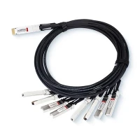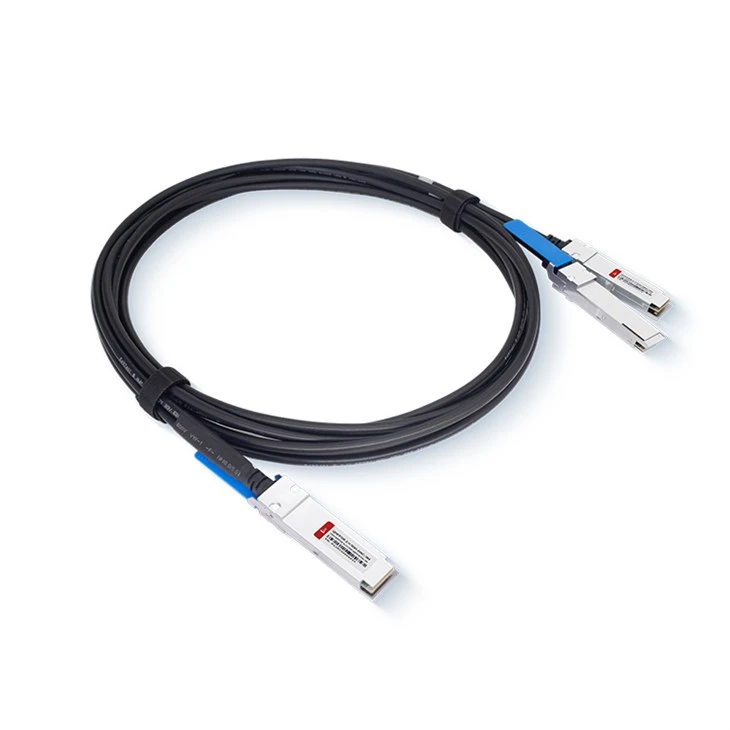
Product Features
● Compliant with CMIS and OSFP_MSA standards
● Ethernet compliant with IEEE 802.3ck
● Supports 112G (PAM4) data rates per channel
● Features an easy-to-control I2C two-line interface
● Supports hot plugging
● Low crosstalk and power consumption
● Maximum link length of up to 3 meters
● Compliant with ROHS regulations
Applications
● Telecommunications equipment
● Servers ,Routers ,Switches
● Central office ,Cellular infrastructure
● Servers ,Storage
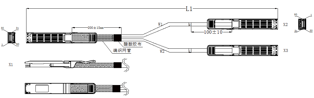
Outline drawing
|
M.P/N |
C.P/N |
L1(mm) |
AWG |
|
O2O112P-005301-001 |
TBD |
500±15 |
30 |
|
O2O112P-010301-001 |
TBD |
1000±25 |
30 |
|
O2O112P-015281-001 |
TBD |
1500±30 |
28 |
|
O2O112P-020281-001 |
TBD |
2500±35 |
28 |
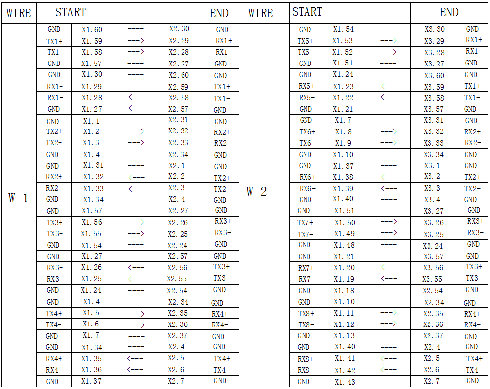
Wiring Diagram
Electrical Performance
Signal Integrity:
|
(ITEM) |
(REQUIREMENT) |
(TEST CONDITION) |
|
|
(Differential Impedance) |
Cable Impedance |
100±5Ω |
Rise time of 25ps (20 % - 80 %). |
|
Paddle Card Impedance |
100±10Ω |
||
|
Cable Termination Impedance |
100±10Ω |
||
|
[Differential (Input/Output)Return loss SDD11/SDD22] |
Return_loss(f)≥16.5-2√f 0.05≤f﹤4.1 10.66-14log10(f/ 5.5) 4.1≤f≤40 Where f is the frequency in GHz Return loss(f) is the return loss at frequency f |
10MHz≤f ≤ |
|
|
[Differential to common-mode (Input/Output)Return loss SCD11/SCD22] |
Return_loss(f)≥ 22-10(f/26.56) 0.05≤f﹤26.56 15-3(f/26.56) 26.56≤f≤40 Where f is the frequency in GHz Return_loss(f) is the Differential to common-mode return loss at frequency f |
50MHz≤f ≤40GHz |
|
[Common-mode to Common-mode (Input/Output)Return loss SCC11/SCC22] |
Return_loss(f)≥1.8dB 0.05≤f≤40 Where f is the frequency in GHz Return_loss(f) is the common-mode to common-mode return loss at frequency f
|
50MHz≤f ≤40GHz |
|
[Differential Insertion Loss (SDD21 Max.)] |
(Differential InsertionLoss Max. For TPa to TPb Excluding Test fixture ) |
50MHz≤f ≤40GHz |
|
Insertion _loss(f)≥-19.75dB 0.05≤f≤26.56 Where f is the frequency in GHz Insertion Loss (f) Differential Insertion Loss at frequency f
|
||
|
[Insertion Loss Deviation] |
-0.176*f - 0.7 ≤ ILD ≤ 0.176* f + 0.7 |
50MHz≤f ≤26.56GHz |
|
Differential to common-mode Conversion Loss-Differential Insertion Loss(SCD21-SDD21) |
Conversion _loss(f) – IL(f)≥10 0.05≤f﹤12.89 14-0.3108f 12.89≤f﹤40 Where f is the frequency in GHz Conversion_loss(f ) is the cable assembly differential to common-mode conversion loss IL(f) is the cable assembly insertion loss |
50MHz≤f ≤40GHz |
|
[MDNEXT(multiple disturber near-end crosstalk)] |
≥35dB @26.5GHz |
10MHz≤f ≤26.5GHz |
|
[Intra Skew] |
10ps/m, |
10MHz≤f ≤26.5GHz |
Other Electrical Performance:
|
(ITEM) |
(REQUIREMENT) |
(TEST CONDITON) |
|
[Low Level Contact Resistance] |
70milliohms Max. From initial. |
EIA-364-23:Apply a maximum voltage of 20mV And a current of 100 mA. |
|
Insulation Resistance |
10Mohm(Min.) |
EIA364-21:AC 300V 1minute |
|
[Dielectric Withstanding Voltage] |
NO disruptive discharge. |
EIA-364-20:Apply a voltage of 300 VDC for 1minute between adjacent terminals And between adjacent terminals and ground. |
Environment Performance
|
(ITEM) |
(REQUIREMENT) |
(TEST CONDITON) |
|
[Operating Temp. Range] |
0°C to +70°C |
Cable operating temperature range. |
|
[Storage Temp. Range (in packed condition)] |
-40°C to +85°C |
Cable storage temperature range in packed condition. |
|
[Thermal Cycling Non-Powered] |
No evidence of physical damage |
EIA-364-32D, Method A, -25 to 90C, 100 cycles, 15 min. dwells |
|
[Salt Spraying] |
48 hours salt spraying after shell corrosive area less than 5%. |
EIA-364-26 |
|
Mixed Flowing Gas |
Pass electrical tests per 3.1 after stressing. (For connector only) |
EIA-364-35 Class II,14 days. |
|
Temp. Life |
No evidence of physical damage |
EIA-364-17C w/ RH, Damp heat 90℃ at 85% RH for 500 hours then return to ambient |
|
Cable Cold Bend |
4H,No evidence of physical damage |
Condition: -20℃±2℃, mandrel diameter is 6 times the cable diameter. |
Mechanical and Physical Characteristics
|
(ITEM) |
(REQUIREMENT) |
(TEST CONDITON) |
|
Vibration |
Pass electrical tests per 3.1 after stressing. |
Clamp & vibrate per EIA-364-28E, TC-VII, test condition letter – D, 15 minutes in X, Y & Z axis. |
|
Cable Flex |
No evidence of physical damage |
Flex cable 180° for 20 cycles (±90° from nominal position) at 12 cycles per minute with a 1.0kg load applied to the cable jacket. Flex in the boot area 90º in each direction from vertical. Per EIA-364-41C |
|
Retention in Cage |
125N Min (OSFP) No evidence of physical damage |
No functional damage to module, connector, or cage with latching mechanism activated. . Per OSFP _Specification_Rev5 |
|
Cable Retention in Plug |
90N Min. No evidence of physical damage |
Cable plug is fixtured with the bulk cable hanging vertically. A 90N axial load is applied (gradually) to the cable jacket and held for 1 minute. Per EIA-364-38B |
|
Mechanical Shock |
Pass electrical tests Per 3.1 after stressing. |
Clamp and shock per EIA-364-27B, TC-G,3 times in 6 directions, 100g, 6ms. |
|
Cable Plug Insertion |
40N Max.(55N) OSFP |
Module to be inserted into connector and cage with latch mechanism engaged. (55N if the cage has riding heatsink) Per OSFP _Specification_Rev5 |
|
Cable plug Extraction |
30N Max. (45N) OSFP |
Module to be removed from connector and cage with latching mechanism disengaged. (45N if the cage has riding heatsink) Per OSFP _Specification_Rev5_0 5.0 |
|
Durability |
50 cycles,No evidence of physical damage |
EIA-364-09, perform plug &unplug cycles:Plug and receptacle mate rate: 250times/hour. 50times for QSFP28/SFP28 module (CONNECTOR TO PCB) |
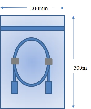
Package diagram
Both ends of the connector use protective sleeve protection, each into a separate anti - static bag.
<=2m : 200mm*300mm
Products Description

FAQ
1. What is the maximum transmission rate supported by this cable?
A: The maximum transmission rate supported by this cable is 800Gbps. It converts 8 channels of 100G-PAM4 signals into two sets of 4 channels of 100G-PAM4 signals.
2. What are the key features of this cable?
A: Key features include low latency, low insertion loss, low crosstalk, and high-speed interconnect. It also undergoes rigorous testing to ensure full compatibility with NVIDIA QM9700/9790 equipment.
3.Does this cable require external power to operate?
A: No, this is a passive direct attach copper cable, meaning it does not require external power to operate and provides a low-latency, low-loss connection.
Hot Tags: 800G OSFP To 2X 400G OSFP112 Breakout DAC, China 800G OSFP To 2X 400G OSFP112 Breakout DAC manufacturers, suppliers, factory, SFP-10G-ZR, QSFP28-100G-LR4, SFP-10G-DWDM-C60-40, dac breakout cable for audio mixing production, SFP-10G-CWDM-1270-10, SFPDD 100G DAC 1 10 M