


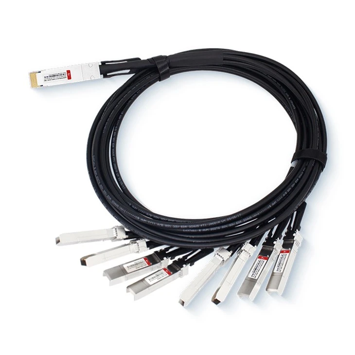
D-Net`S DAC Breakout Cables Service
● Compatibility Assistance: D-NET offers compatibility services to ensure optical modules are compatible with equipment from leading manufacturers.
● Personalized Services: D-NET provides OEM customization options for its products. Upon request, customers can have colored logo labels tailored to their needs.
● Standard Delivery Period: 3 Days
● Extensive Shipping Solutions: D-NET collaborates with highly reputable courier companies such as SF, FedEx, DHL, UPS, and others to ensure reliable shipping services.
Product Features
● The product complies with sff-8636 and sff-8402
● The product conforms to Ethernet IEEE802.3bj/IEEE 802.3cd
● Product complies with qsfp DD MSA
● Supports hot insertion
● Low crosstalk
● low power consumption
● RoHS compliant products
Applications
● 10g / 40g / 100g / 200g / 400g Ethernet
● Infiniband SDR, DDR, QDR,FDR,EDR
● Switch
● Router
● Data center, cloud server
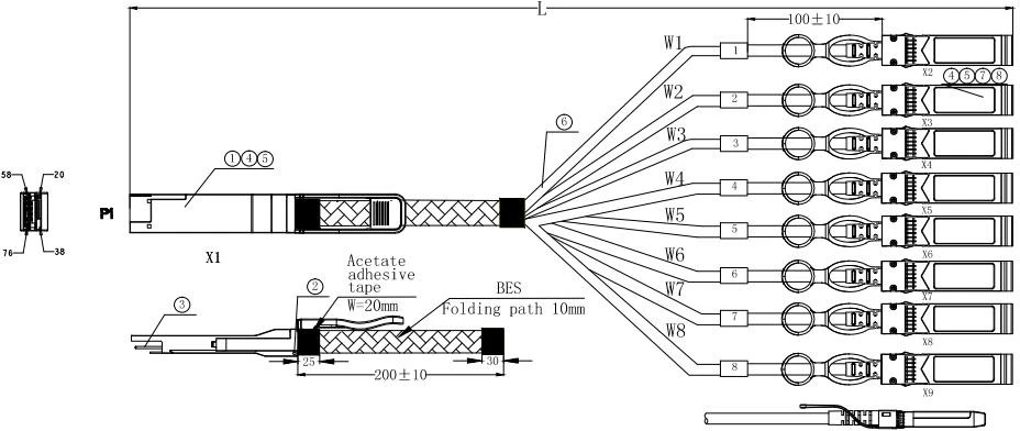
Outline drawing
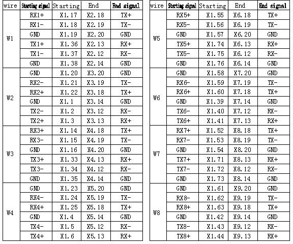
Wiring Diagram
Electrical Performance
Signal Integrity:
|
ITEM |
REQUIREMENT |
TEST CONDITION |
|||||||
|
Differenti al Impedan ce |
Cable Impedance |
105+5/-10Ω |
Rise time of 25ps (20 % - 80 %). |
||||||
|
Paddle Card Impedance |
100±10Ω |
||||||||
|
Cable Termination Impedance |
100±15Ω |
||||||||
|
Differential (Input/Output)Return loss SDD11/SDD22 |
Return_loss(f)≥ 16.5-2√f 0.05≤f﹤4.1 10.66-14log10(f/ 5.5) 4.1≤f≤19 Where f is the frequency in GHz Return loss(f) is the return loss at frequency f |
10MHz≤f ≤19GHz |
|||||||
|
Differential to common-mode (Input/Output)Return loss SCD11/SCD22 |
Return_loss(f)≥ 22-(20/25.78)f 0.01≤f﹤12.89 15-(6/25.78)f 12.89≤f≤19 Where f is the frequency in GHz Return_loss(f) is the Differential to common-mode return loss at frequency f |
10MHz≤f ≤19GHz |
|||||||
|
Common-mode to Common-mode (Input/Output)Return loss SCC11/SCC22 |
Return_loss(f)≥2dB 0.2≤f≤19 Where f is the frequency in GHz Return_loss(f) is the common-mode to common-mode return loss at frequency f |
10MHz≤f ≤19GHz |
|||||||
|
Differential Insertion Loss (SDD21 Max.) |
(Differential InsertionLoss Max. For TPa to TPb Excluding Test fixture ) |
10MHz≤f ≤19GHz |
|||||||
|
F AWG |
1.25GHz |
2.5GHz |
5.0GHz |
7.0GHz |
10Ghz |
12.89Ghz |
|||
|
30(1m) Max. |
4.5dB |
5.4dB |
6.3dB |
7.5dB |
8.5dB |
10.5dB |
|||
|
30/28( 3m)Ma x. |
7.5dB |
9.5dB |
12.2dB |
14.8dB |
18.0dB |
21.5dB |
|||
|
26(3m) Max. |
5.7dB |
7.2dB |
9.9 dB |
11.9dB |
14.1dB |
16.5dB |
|||
|
26/25( 5m)Ma x. |
7.8dB |
10.0dB |
13.5dB |
16.0dB |
19.0dB |
22.0dB |
|||
|
Differential to common-mode Conversion Loss-Differential Insertion Loss(SCD21-SDD21) |
Conversion _loss(f) – IL(f)≥10 0.01≤f﹤ 12.89
Where f is the frequency in GHz Conversion_loss(f ) is the cable assembly differential to common-mode conversion loss IL(f) is the cable assembly insertion loss |
10MHz≤f ≤19GHz |
||||||
|
[MDNEXT(multiple disturber near-end crosstalk)] |
≥26dB @12.89GHz |
10MHz≤f ≤19GHz |
||||||
Other Electrical Performance:
|
TEM |
REQUIREMENT |
TEST CONDITON |
|
Low Level Contact Resistance |
70milliohms Max. From initial. |
EIA-364-23:Apply a maximum voltage of 20mV And a current of 100 mA. |
|
Insulation Resistance |
10Mohm(Min.) |
EIA364-21:AC 300V 1minute |
|
Dielectric Withstanding Voltage |
NO disruptive discharge. |
EIA-364-20:Apply a voltage of 300 VDC for 1minute between adjacent terminals And between adjacent terminals and ground. |
nvironment Performance
|
ITEM |
REQUIREMENT |
EST CONDITON |
|
Operating Temp. Range |
-20°C to +75°C |
Cable operating temperature range. |
|
Storage Temp. Range (in packed condition)] |
-40°C to +80°C |
Cable storage temperature range in packed condition. |
|
Thermal Cycling Non-Powered |
No evidence of physical damage |
EIA-364-32D, Method A, -25 to 90C, 100 cycles, 15 min. dwells |
|
Salt Spraying |
48 hours salt spraying after shell corrosive area less than 5%. |
EIA-364-26 |
|
Mixed Flowing Gas |
Pass electrical tests per 3.1 after stressing. (For connector only) |
EIA-364-35 Class II,14 days. |
|
Temp. Life |
No evidence of physical damage |
EIA-364-17C w/ RH, Damp heat 90℃ at 85% RH for 500 hours then return to ambient |
|
Cable Cold Bend |
4H,No evidence of physical damage |
Condition: -20℃±2℃, mandrel diameter is 6 times the cable diameter. |
Mechanical and Physical Characteristics
|
ITEM |
REQUIREMENT |
TEST CONDITON |
|
Vibration |
Pass electrical tests per 3.1 after stressing. |
Clamp & vibrate per EIA-364-28E, TC-VII, test condition letter – D, 15 minutes in X, Y & Z axis. |
|
Cable Flex |
No evidence of physical damage |
Flex cable 180° for 20 cycles (±90° from nominal position) at 12 cycles per minute with a 1.0kg load applied to the cable jacket. Flex in the boot area 90º in each direction from vertical. Per EIA-364-41C |
|
Cable Plug Retention in Cage |
90N Min. No evidence of physical damage |
Force to be applied axially with no damage to cage. Per SFF 8661 Rev 2.1 Pull on cable jacket approximately 1 ft behind cable plug. No functional damage to cable plug below 90N. Per SFF-8432 Rev 5.0 |
|
Cable Retention in Plug |
90N Min. No evidence of physical damage |
Cable plug is fixtured with the bulk cable hanging vertically. A 90N axial load is applied (gradually) to the cable jacket and held for 1 minute. Per EIA-364-38B |
|
Mechanical Shock |
Pass electrical tests Per 3.1 after stressing. |
Clamp and shock per EIA-364-27B, TC-G,3 times in 6 directions, 100g, 6ms. |
|
Cable Plug Insertion |
40N Max.(QSFP DD) 18N Max.(SFP28) |
Per SFF8661 Rev 2.1 Per SFF-8432 Rev 5.0 |
|
Cable plug Extraction |
30N Max. (QSFP DD) 12.5N Max. (SFP28) |
Place axial load on de-latch to de-latch plug.Per SFF8661 Rev 2.1 Measure without the aid of any cage kick-out springs. Place axial load on de-latch to de-latch plug. Per SFF-8432 Rev 5.0 |
|
Durability |
50 cycles,No evidence of physical damage |
EIA-364-09, perform plug &unplug cycles:Plug and receptacle mate rate: 250times/hour. 50times for QSFP DD/SFP28 module (CONNECTOR TO PCB) |
Package diagram
a. The connectors at both ends are protected by protective sleeves, and each put into a silver gray anti-static bag.
b. Put a label in the middle of the silver gray anti-static bag.
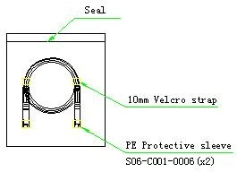
c. Two labels on the carton(As shown in the figure below)

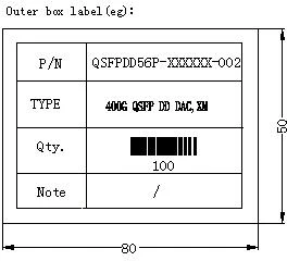
Schematic diagram of label pasting Schematic diagram of outer box label
Products Description
|
Length |
M.P/N |
AWG |
Length Tolerance (mm) |
|
0.5m |
QDD8S56P-005301-004 |
30 |
±15 |
|
1m |
QDD8S56P-010301-004 |
30 |
±25 |
|
1.5m |
QDD8S56P-015301-004 |
30 |
±30 |
|
2m |
QDD8S56P-020281-004 |
28 |
±30 |
|
2.5m |
QDD8S56P-025281-004 |
28 |
±45 |
|
3m |
QDD8S56P-030281-004 |
28 |
±45 |
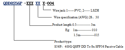
FAQ
1. What is the significance of the breakout configuration from QSFP-DD to 8x50G SFP56?
A: The breakout configuration allows a single high-capacity QSFP-DD port to be split into eight individual 50G SFP56 ports, providing greater flexibility in network design and enabling the use of smaller, more granular interfaces.
2. Can this DAC cable be used in outdoor or harsh environment applications?
A: DAC cables are typically designed for indoor, controlled environment applications within data centers. They are not suitable for outdoor or harsh environment applications due to their sensitivity to environmental factors like temperature, humidity, and dust.
3. What kind of connector is used on both ends of the DAC cable?
A: One end of the DAC cable uses a QSFP-DD connector, while the other end features eight individual SFP56 connectors.
Hot Tags: 400g qsfp-dd to 8x50g sfp56 breakout dac direct attach copper cable, China 400g qsfp-dd to 8x50g sfp56 breakout dac direct attach copper cable manufacturers, suppliers, factory, SFP-1G-ER, SFP28-DWDM-C21, QSFP28-100G-LR4, SFP-10G-ER, QSFP56-200G-AOC, QSFP-40G-LR4


