")
")
")
")
Product details
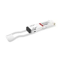
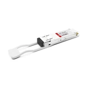
D-NET's 100G QSFP28 SR4 module is engineered to function within multi-mode fiber systems utilizing an 850nm VCSEL laser array. The module receptacle is compatible with an optical fiber ribbon cable equipped with an MPO/MTPTM connector. The 100G SR4 transceiver belongs to the category of parallel transceivers, offering enhanced port density and overall system cost savings.
Hot Tags: QSFP28 100G SR4 MPO12 transceiver module, China QSFP28 100G SR4 MPO12 transceiver module manufacturers, suppliers, factory, QSFP28-100G-ER4, QSFP28-100G-SR4, QSFP28-100G-LR4, QSFP28-100G-LR4, , QSFP28-100G-ZR4
Absolute Maximum Ratings
The operation in excess of any absolute maximum ratings might cause permanent damage to this module.
| Parameter | Symbol | Min | Max | Unit | Notes |
| Storage Temperature | TS | -40 | 85 | degC | |
| Relative Humidity(non-condensation) | RH | 5 | 90 | % | |
| Operating Case Temperature | TOP | 0 | 70 | degC | |
| Supply Voltage | VCC | -0.3 | 3.6 | V | |
| Input Voltage | Vin | -0.3 | Vcc+0.3 | V |
Recommended Operating Conditions and Power Supply Requirements
| Parameter | TestPoint | Min | Typical | Max | Unit | Notes |
| Operating Case Temperature | TOP | 0 | 70 | degC | Operating Case Temperature | |
| Power Supply Voltage | VCC | 3.13 | 3.3 | 3.47 | V | Power Supply Voltage |
| Power Consumption | - | 2.5 | W | Power Consumption | ||
| Data Rate | DR | 25.78125 | Gbps | Data Rate | ||
| Data Speed Tolerance | ∆DR | -100 | 100 | ppm | Data Speed Tolerance | |
| Link Distance with G.652 | D | 0 | 70 | m | LinkDistancewithOM3 fiber |
Electrical Characteristics
| Parameter | TestPoint | Min | Typical | Max | Unit | Notes |
| Differential input impedance | Zin | 90 | 100 | 110 | ohm | |
| Differential Output impedance | Zout | 90 | 100 | 110 | ohm | |
| Differential input voltage amplitude | ΔVin | 300 | 1100 | mVp-p | ||
| Differential output voltage amplitude | ΔVout | 300 | 800 | mVp-p | ||
| Bit Error Rate | BR | 5.00E-05 | ||||
| Input Logic Level High | VIH | 2 | VCC | V | ||
| Input Logic Level Low | VIL | 0 | 0.8 | V | ||
| Output Logic Level High | VOH | VCC-0.5 | VCC | V | ||
| Output Logic Level Low | VOL | 0 | 0.4 | V |
Optical Characteristics
| Parameter |
Symbol |
Min |
Typical |
Max |
Unit |
Notes |
|
Transmitter |
||||||
|
Center Wavelength |
λC |
840 |
850 |
860 |
nm |
1 |
|
RMS Spectral Width |
λrms |
- |
|
0.65 |
nm |
1 |
|
Average Launch Power,each lane |
PAVG |
-8.4 |
|
2.4 |
dBm |
|
|
Optical Modulation Amplitude(OMA) |
POMA |
-6.4 |
|
3 |
dBm |
1 |
|
Difference in Launch Power between |
Ptx,diff |
|
|
4 |
dB |
|
|
Any two lanes Launch Power in OMA minus Transmitter and Dispersion Penalty (TDP),each Lane |
OMA-TDP |
|
|
3.5 |
dBm |
1 |
|
Extinction Ratio |
ER |
2 |
|
|
dB |
|
|
Transmitter Eye Mask Margin |
EMM |
10 |
|
|
% |
2 |
|
Average Launch Power OFF Transmitter, each Lane |
Poff |
|
|
-30 |
dBm |
|
|
Transmitter Eye Mask Definition {X1, X2, X3, Y1, Y2, Y3} |
|
{0.3,0.38,0.45,0.35,0.41,0.5} |
|
|
|
|
|
Receiver |
|||||
|
Center Wavelength |
λC |
840 |
850 |
860 |
nm |
|
Damage Threshold |
THd |
3 |
|
|
dBm |
|
Overload,each lane |
OVL |
2.4 |
|
|
dBm |
|
Receiver Sensitivity in OMA,each Lane |
SEN |
|
|
-5.2 |
dBm |
|
Signal Loss Assert Threshold |
LOSA |
-30 |
|
|
dBm |
|
Signal Loss Deassert Threshold |
LOSD |
|
|
-13 |
dBm |
|
LOS Hysteresis |
LOSH |
0.5 |
|
6 |
dB |
|
Optical Return Loss |
ORL |
|
|
-12 |
dBm |
Ordering Information
|
Part Number |
Description |
|
QSFP28-SR4 |
QSFP28 100G SR4 MPO12 transceiver module,MPO connector,70M on OM3 |
FAQ
- What does QSFP28 mean ?
A: QSFP28 is a Quad (4-channel) small form factor hot pluggable fibre optical transceiver used for 100 Gigabit Ethernet (100GbE) data communications applications.
- What is 100G SR4 transceiver?
A :D-net Transceiver for IEEE 802.3bm,100GBASE SR4 Applications. The QSFP28 full-duplex optical module offers 4 independent transmit and receive channels, each capable of 25.78125Gbps operation for an aggregate data rate of 103.125Gbps 100m using OM4 fiber.
- What is SR4 connector?
A:The optical interface port is a male MPO connector.The four fiber positions on the left ,with the key up,are used for the optical transmit signals(Channel1through4). The fiber positions on the right are used for the optical receive signals