


Product Details
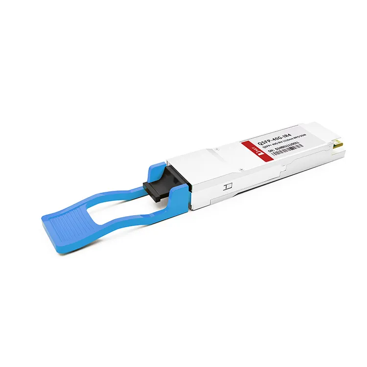
D-NET's QSFP+ 40G IR4 converts four input channels of 10Gb/s electrical data into four optical signals, which are then multiplexed into a single channel for 40Gb/s optical transmission. Conversely, on the receiver side, the QSFP+ 40G 10KM module optically demultiplexes a 40Gb/s input into four separate channel signals and converts them back into four output channels of electrical data. To minimize optical dispersion in long-haul systems, this transceiver module must utilize single-mode fiber (SMF).
D-NET is a supplier that specializes in the optical communication industry. The production process of the QSFP+ 40G 10KM is meticulously supervised at every stage, and the products undergo rigorous testing by staff to guarantee their normal operation and reliable quality. Each product is backed by a 3-year warranty.
Hot Tags: QSFP+ 40G IR4 10KM transceiver module, China QSFP+ 40G IR4 10KM transceiver module manufacturers, suppliers, factory, QSFP-40G-ZR4, QSFP-40G-SR4, QSFP-40G-ER4, QSFP-40G-IR4, QSFP-40G-ZR4, QSFP-40G-LR4
Absolute Maximum Ratings
|
Parameter |
Symbol |
Min. |
Typical |
Max. |
Unit |
|
Storage Temperature |
TS |
-40 |
+85 |
°C |
|
|
Supply Voltage |
VCCT, R |
-0.5 |
4 |
V |
|
|
Relative Humidity |
RH |
0 |
85 |
% |
Recommended Operating Environment
|
Parameter |
Symbol |
Min. |
Typical |
Max. |
Unit |
|
Case operating Temperature |
TC |
0 |
+70 |
°C |
|
|
Supply Voltage |
VCCT, R |
+3.13 |
3.3 |
+3.47 |
V |
|
Supply Current |
ICC |
1000 |
mA |
||
|
Power Dissipation |
PD |
3.5 |
W |
Electrical Characteristics
(TOP = 0 to 70 °C, VCC = 3.13 to 3.47 Volts)
|
Parameter |
Symbol |
Min |
Typ |
Max |
Unit |
Note |
|
Data Rate per Channel |
- |
10.3125 |
11.2 |
Gbps |
||
|
Power Consumption |
- |
2.5 |
3.5 |
W |
||
|
Supply Current |
Icc |
0.75 |
1.0 |
A |
||
|
Control I/O Voltage-High |
VIH |
2.0 |
Vcc |
V |
||
|
Control I/O Voltage-Low |
VIL |
0 |
0.7 |
V |
||
|
Inter-Channel Skew |
TSK |
150 |
Ps |
|||
|
RESETL Duration |
10 |
Us |
||||
|
RESETL De-assert time |
100 |
ms |
||||
|
Power On Time |
100 |
ms |
||||
|
Transmitter |
||||||
|
Single Ended Output Voltage Tolerance |
0.3 |
4 |
V |
1 |
||
|
Common mode Voltage Tolerance |
15 |
mV |
||||
|
Transmit Input Diff Voltage |
VI |
150 |
1200 |
mV |
||
|
Transmit Input Diff Impedance |
ZIN |
85 |
100 |
115 |
||
|
Data Dependent Input Jitter |
DDJ |
0.3 |
UI |
|||
|
Receiver |
||||||
|
Single Ended Output Voltage Tolerance |
0.3 |
4 |
V |
|||
|
Rx Output Diff Voltage |
Vo |
370 |
600 |
950 |
mV |
|
|
Rx Output Rise and Fall Voltage |
Tr/Tf |
35 |
ps |
1 |
||
|
Total Jitter |
TJ |
0.3 |
UI |
|||
Note: 20~80%
Optical Parameters
(TOP = 0 to 70 °C, VCC = 3.0 to 3.6 Volts)
|
Parameter |
Symbol |
Min |
Typ |
Max |
Unit |
Ref. |
|
Transmitter |
||||||
|
Wavelength Assignment |
1300 |
1311 |
1320 |
nm |
||
|
Side-mode Suppression Ratio |
SMSR |
30 |
- |
- |
dB |
|
|
Average Optical Power per Channel |
-5 |
- |
+1 |
dBm |
||
|
TDP, each Lane |
TDP |
2.3 |
dB |
|||
|
Extinction Ratio |
ER |
3.5 |
- |
- |
dB |
|
|
Transmitter Eye Mask Definition {X1, X2, X3, Y1, Y2, Y3} |
{0.25, 0.4, 0.45, 0.25, 0.28, 0.4} |
|||||
|
Optical Return Loss Tolerance |
- |
- |
20 |
dB |
||
|
Average Launch Power OFF Transmitter, each Lane |
Poff |
-30 |
dBm |
|||
|
Relative Intensity Noise |
Rin |
-128 |
dB/HZ |
1 |
||
|
Optical Return Loss Tolerance |
- |
- |
12 |
dB |
||
|
Receiver |
||||||
|
Damage Threshold |
THd |
3.3 |
dBm |
1 |
||
|
Average Power at Receiver Input, each Lane |
R |
-12.6 |
0 |
dBm |
||
|
Receive Electrical 3 dB upper Cut off Frequency, each Lane |
12.3 |
GHz |
||||
|
RSSI Accuracy |
-2 |
2 |
dB |
|||
|
Receiver Reflectance |
Rrx |
-26 |
dB |
|||
|
Receiver Power (OMA), each Lane |
- |
- |
3.5 |
dBm |
||
|
Receive Electrical 3 dB upper Cutoff Frequency, each Lane |
12.3 |
GHz |
||||
|
LOS De-Assert |
LOSD |
-13 |
dBm |
|||
|
LOS Assert |
LOSA |
-25 |
dBm |
|||
|
LOS Hysteresis |
LOSH |
0.5 |
dB |
|||
Note: 12dB Reflection
Ordering Information
|
Part Number |
Description |
|
40G-IR4 |
QSFP+ 40G IR4 10KM transceiver module with full real- time digital diagnostic monitoring and pull tab |
FAQ
1. What is QSFP+ 40G IR4?
A: D-NET's 40G IR4 is a transceiver module designed for 10km optical communication applications,It has 4 independent full-duplex channels with bandwidth up to 11.2Gbps per channel,is a high performance, low power consumption, long distance interconnection solution.
2. When to use QSFP+ 40G IR4 10KM transceiver module?
A: D-NET's QSFP+ 40G IR4 transceiver module is widely used in switches and routers in data centers and in 40G BASE-LR4-PSM Ethernet links.
3. How to use MTP/MPO cables to connect QSFP+ 40G IR4 Optical Transceiver?
A: Usually, the MTP/MPO interface socket has a guide pin, which can be used to align the correct interface when the module is inserted. When the user inserts the fiber jumper with MTP/MPO connector into the QSFP+ 40G 10KM optical module, it can avoid the problem of fiber damage due to the failure of the interface.


