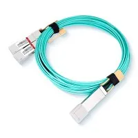
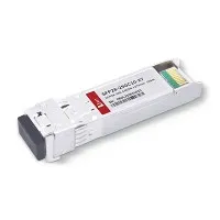
Features
• Compliant with the SFP+ Multi-Source Agreement (SFF-8432)
• Adheres to IEEE 802.3ae standards
• Features optimized NEXT (Near-End Cross-Talk) and Return Loss performance
• Enhanced EMI (Electromagnetic Interference) / EMC (Electromagnetic Compatibility) capabilities
• Supports serial ID functionality through an EEPROM (Electrically Erasable Programmable Read-Only Memory)
• Passive cable assembly capable of supporting lengths up to 10 meters
• Cable sizes ranging from 30AWG to 24AWG are available
• Compliant with RoHS standards, with a Halogen-Free option also available
Applications
• Fiber Channel with capacities ranging from 1 to 8G and Gigabit Ethernet with speeds from 1 to 10G
• Hubs, Switches, Routers, Servers, and Network Interface Cards (NICs)
• Cabling infrastructure for data centers
• Networking, Storage solutions, and Telecommunications systems
Outline drawing
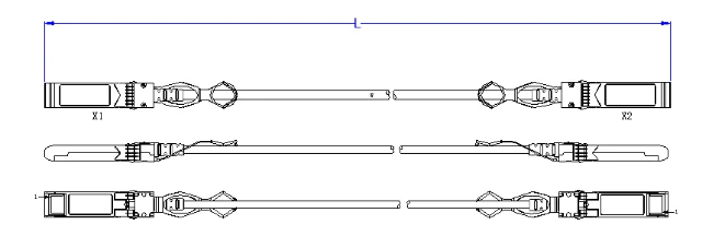
Wiring Diagram
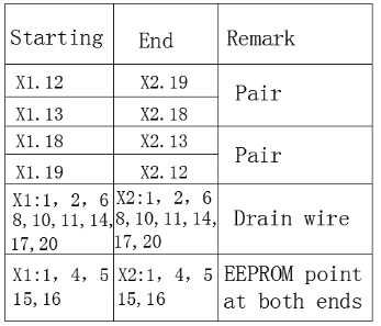
Electrical Performance
Signal Integrity:
|
(ITEM) |
(REQUIREMENT) |
(TEST CONDITION) |
|||||
|
(Differential Impedance) |
Cable Impedance |
105+5/-5Ω |
Rise time of 35ps (20 % - 80 %). |
||||
|
Paddle Card Impedance |
100±10Ω |
||||||
|
Cable Termination Impedance |
100±15Ω |
||||||
|
[Differential (Input/Output)Return loss SDD11/SDD22] |
Return loss(f)≥10 0.01≤f﹤4.1 6.3-13log10(f/ 5.5) 4.1≤f≤11.1 Where f is the frequency in GHz Return loss(f) is the return loss at frequency f |
0.01GHz≤f≤11.1GHz SFF-8431 Rev.4.1 |
|||||
|
[Differential Insertion Loss (SDD21 Max.)] |
(Differential Insertion Loss Max.) |
0.01GHz≤f≤11.1GHz |
|||||
|
F AWG |
600MHz |
1.25GHz |
2.5GHz |
5.0GHz |
|||
|
30(1m)Max |
2.5dB |
3.5dB |
4.5dB |
6.5dB |
|||
|
30(2m)Max |
3.8dB |
5.3dB |
6.8dB |
9.8dB |
|||
|
30(3m)Max |
5.0dB |
7.0dB |
9.0dB |
13.0dB |
|||
|
26(5m)Max |
5.5dB |
7.0dB |
10.5dB |
15.0dB |
|||
|
24( 7m)Ma |
6.5dB |
9.2dB |
12.5dB |
17.04dB |
|||
|
24(10m)Max |
7.0dB |
10.0dB |
14.0dB |
20.0dB |
|||
|
[MDNEXT(multiple disturber near-end crosstalk)] |
≥26dB @5GHz |
0.01GHz≤f≤11.1GHz |
|||||
|
[Insertion Loss Deviation] |
-0.7-0.2*10-3f ≤ ILD ≤ 0.7+0.2*10-3f (f is the frequency in MHz) |
0.01GHz≤f≤5.0GHz |
|||||
Other Electrical Performance:
|
(ITEM) |
(REQUIREMENT) |
(TEST CONDITON) |
|
[Low Level Contact Resistance] |
70milliohms Max. From initial. |
EIA-364-23:Apply a maximum voltage of 20mV And a current of 100 mA. |
|
Insulation Resistance |
10Mohm(Min.) |
EIA364-21:AC 300V 1minute |
|
[Dielectric Withstanding Voltage] |
DC 500V 1 minute disruptive discharge. |
EIA-364-20:Apply a voltage of 500 VDC for 1minute between adjacent terminals And between adjacent terminals and ground. |
Environment Performance
|
(ITEM) |
(REQUIREMENT) |
(TEST CONDITON) |
|
[Operating Temp. Range] |
-20°C to +75°C |
Cable operating temperature range. |
|
Storage Temp. Range (in packed condition)] |
-20°C to +55°C |
Cable storage temperature range in packed condition. |
|
[Thermal Cycling Non-Powered] |
No evidence of physical damage |
EIA-364-32D, Method A, -25 to 90C, 100 cycles, 15 min. dwells |
|
[Salt Spraying] |
48 hours salt spraying after shell corrosive area less than 5%. |
EIA-364-26 |
|
Mixed Flowing Gas |
Pass electrical tests per 3.1 after stressing. (For connector only) |
EIA-364-35 Class II,14 days. |
|
Temp. Life |
No evidence of physical damage |
EIA-364-17C w/ RH, Damp heat 90℃ at 85% RH for 500 hours then return to ambient |
|
Cable Cold Bend |
4H,No evidence of physical damage |
Condition: -20℃±2℃, mandrel diameter is 6 times the cable diameter. |
Mechanical and Physical Characteristics
|
(ITEM) |
(REQUIREMENT) |
(TEST CONDITON) |
|
Vibration |
Pass electrical tests per 3.1 after stressing. |
Clamp & vibrate per EIA-364-28E, TC-VII, test condition letter – D, 15 minutes in X, Y & Z axis. |
|
Cable Flex |
No evidence of physical damage |
Flex cable 180° for 20 cycles (±90° from nominal position) at 12 cycles per minute with a 1.0kg load applied to the cable jacket. Flex in the boot area 90º in each direction from vertical. Per EIA-364-41C |
|
Cable Plug Retention in Cage |
90N Min. No evidence of physical damage |
Pull on cable jacket approximately 1 ft behind cable plug. No functional damage to cable plug below 90N. Per SFF-8432 Rev 5.0 |
|
Cable Retention in Plug |
90N Min. No evidence of physical damage |
Cable plug is fixtured with the bulk cable hanging vertically. A 90N axial load is applied (gradually) to the cable jacket and held for 1 minute. Per EIA-364-38B |
|
Mechanical Shock |
Pass electrical tests Per 3.1 after stressing. |
Clamp and shock per EIA-364-27B, TC-G,3 times in 6 directions, 100g, 6ms. |
|
Cable Plug Insertion |
18N Max.(SFP28) |
Per SFF-8432 Rev 5.0 |
|
Cable plug Extraction |
12.5N Max. (SFP28) |
Measure without the aid of any cage kick-out springs. Place axial load on de-latch to de-latch plug. Per SFF-8432 Rev 5.0 |
|
Durability |
50 cycles,No evidence of physical damage |
EIA-364-09, perform plug &unplug cycles:Plug and receptacle mate rate: 250times/hour. 50times for module (CONNECTOR TO PC |
FAQ
1. What is the 10G SFP+ Passive DAC Direct Attach Copper Cable?
The 10G SFP+ Passive DAC (Direct Attach Copper) Cable is a high-performance copper cable specifically engineered for short-range data transfer within data centers, capable of achieving speeds up to 10Gbps.
2. Will the 10G SFP+ DAC work plugged into a Cisco Switch/router?
A: Yes, the 10G SFP+ DAC can work when plugged into a Cisco Switch/Router, as long as it is compatible with the specific model and configuration of the Cisco equipment.
3. Are 10G SFP+ Passive DAC cables hot-pluggable?
A: Yes, most 10G SFP+ Passive DAC cables are designed to be hot-pluggable, allowing you to connect or disconnect them without powering down the equipment.
Hot Tags: 10g sfp+ passive dac direct attach copper cable, China 10g sfp+ passive dac direct attach copper cable manufacturers, suppliers, factory, SFP28-25G-SR, QSFP-40G-ZR4, SFP-10G-DWDM-C60-80, SFP-10G-ZR, Mechanical Optical Switch