Products Features
● Supports 4x25GBASE-SR applications
● Compliant with QSFP28 MSA SFF-8636, SFP28 MSA SFF-8431, and SF-8472 specifications
● Offers a multi-rate capability of up to 25.78125Gbps per lane
● Operates with a +3.3V single power supply
● Features low power consumption
● UL-certified cables available as an option
● Commercial operating case temperature range: 0°C to +70°C
● Compliant with RoHS standards
Applications
● Supports 100GBASE-SR4 with a data rate of 25.78125Gbps per lane
● Compatible with InfiniBand QDR and EDR technologies
● Supports other optical link configurations
Outline drawing

|
QSFP28 |
L |
L1 |
L2 |
L3 |
L4 |
W |
W1 |
W2 |
H |
H1 |
H2 |
H3 |
H4 |
H5 |
H6 |
|
Max |
72.2 |
- |
128 |
4.35 |
61.4 |
18.45 |
- |
6.2 |
8.6 |
12.4 |
5.35 |
2.5 |
1.6 |
2.0 |
- |
|
Type |
72.0 |
- |
- |
4.20 |
61.2 |
18.35 |
- |
- |
8.5 |
12.2 |
5.2 |
2.3 |
1.5 |
1.8 |
6.55 |
|
Min |
68.8 |
16.5 |
124 |
4.05 |
61.0 |
18.25 |
2.2 |
5.8 |
8.4 |
12.0 |
5.05 |
2.1 |
1.3 |
1.6 |
- |
|
SFP28 |
L |
L1 |
L2 |
L3 |
W |
W1 |
W2 |
H |
H1 |
A |
|
Max |
57.6 |
47.7 |
44.55 |
119.9 |
13.8 |
14.0 |
12.3 |
8.7 |
10.3 |
45.25 |
|
Type |
57.4 |
47.5 |
44.35 |
117.9 |
13.55 |
13.8 |
12.1 |
8.5 |
10.1 |
45 |
|
Min |
57.2 |
47.3 |
44.15 |
115.9 |
13.3 |
13.6 |
11.9 |
8.4 |
9.9 |
44.65 |
Cable Length
|
Parameter |
Value |
Units |
|
Diameter |
3 |
mm |
|
Minimum bend radius |
30 |
mm |
|
Length tolerance |
Length < 1 m: +5 /-0 |
cm |
|
1 m ≤length ≤ 4.5 m: +15 / -0 |
cm |
|
|
5 m ≤length ≤ 14.5 m: +30 / -0 |
cm |
|
|
Length≥15.0 m +2% / -0 |
m |
|
|
Cable color |
Orange(OM2),Aqua(OM3),Megenta(OM4) |
|
Breakout Cable Nominal Length
|
Total Length X (Unit: m) |
Breakout Point Measured from QSFP LQ (Unit: m) |
Breakout Point Measured from SFP LS(Unit: m) |
|
1 |
0.3 |
0.7 |
|
2 |
0.6 |
1.4 |
|
3 |
1 |
2 |
|
5 |
2 |
3 |
|
7 |
4 |
3 |
|
10 |
7 |
3 |
|
15 |
12 |
3 |
|
20 |
17 |
3 |
|
25 |
22 |
3 |
|
30 |
27 |
3 |
|
40 |
37 |
3 |
|
50 |
47 |
3 |
Pin arrangement

Figure 2 Pin View for QSFP28
Pin Function Definitions for QSFP28
|
Pin |
Symbol |
Name/Description |
Notes |
|
1 |
GND |
Ground |
1 |
|
2 |
Tx2n |
Transmitter Inverted Data Input |
|
|
3 |
Tx2p |
Transmitter Non-Inverted Data Input |
|
|
4 |
GND |
Ground |
1 |
|
5 |
Tx4n |
Transmitter Inverted Data Input |
|
|
6 |
Tx4p |
Transmitter Non-Inverted Data Input |
|
|
7 |
GND |
Ground |
1 |
|
8 |
ModSelL |
Module Select |
|
|
9 |
ResetL |
Module Reset |
|
|
10 |
Vcc Rx |
+3.3V Power Supply Receiver |
|
|
11 |
SCL |
2-wire serial interface clock |
|
|
12 |
SDA |
2-wire serial interface data |
|
|
13 |
GND |
Ground |
1 |
|
14 |
Rx3p |
Receiver Non-Inverted Data Output |
|
|
15 |
Rx3n |
Receiver Inverted Data Output |
|
|
16 |
GND |
Ground |
1 |
|
17 |
Rx1p |
Receiver Non-Inverted Data Output |
|
|
18 |
Rx1n |
Receiver Inverted Data Output |
|
|
19 |
GND |
Ground |
1 |
|
20 |
GND |
Ground |
1 |
|
21 |
Rx2n |
Receiver Inverted Data Output |
|
|
22 |
Rx2p |
Receiver Non-Inverted Data Output |
|
|
23 |
GND |
Ground |
1 |
|
24 |
Rx4n |
Receiver Inverted Data Output |
|
|
25 |
Rx4p |
Receiver Non-Inverted Data Output |
|
|
26 |
GND |
Ground |
1 |
|
27 |
ModPrsL |
Module Present |
|
|
28 |
IntL |
Interrupt |
|
|
29 |
Vcc Tx |
+3.3V Power supply transmitter |
|
|
30 |
Vcc1 |
+3.3V Power supply |
|
|
31 |
LPMode |
Low Power Mode |
|
|
32 |
GND |
Ground |
1 |
|
33 |
Tx3p |
Transmitter Non-Inverted Data Input |
|
|
34 |
Tx3n |
Transmitter Inverted Data Input |
|
|
35 |
GND |
Ground |
1 |
|
36 |
Tx1p |
Transmitter Non-Inverted Data Input |
|
|
37 |
Tx1n |
Transmitter Inverted Data Input |
|
|
38 |
GND |
Ground |
1 |
Note: 1. Circuit ground is internally isolated from chassis ground.

Figure 3 Pin View for SFP28
Pin Function Definitions
|
Pin |
Symbol |
Name/Description |
Notes |
|
1 |
VEET |
Module Transmitter Ground |
1 |
|
2 |
TX_FAULT |
Module Transmitter Fault |
2 |
|
3 |
TX_DISABLE |
Transmitter Disable; Turns off transmitter laser output |
3 |
|
4 |
SDA |
2-Wire Serial Interface Data Line (MOD-DEF2) |
|
|
5 |
SCL |
2-Wire Serial Interface Clock (MOD-DEF1) |
|
|
6 |
MOD_ABS |
Module Absent, connected to VEET or VEER in the module |
2 |
|
7 |
RS0 |
Rate Select 0, optionally controls SFP+ module receiver |
|
|
8 |
RX_LOS |
Receiver Loss of Signal Indication (In FC designated as Rx_LOS and in Ethernet designated as NOT Signal Detect) |
2 |
|
9 |
RS1 |
Rate Select 1, optionally controls SFP+ module transmitter |
|
|
10 |
VEER |
Module Receiver Ground |
1 |
|
11 |
VEER |
Module Receiver Ground |
1 |
|
12 |
RD- |
Receiver Inverted Data Output |
|
|
13 |
RD+ |
Receiver Non-Inverted Data Output |
|
|
14 |
VEER |
Module Receiver Ground |
1 |
|
15 |
VCCR |
Module Receiver 3.3 V Supply |
|
|
16 |
VCCT |
Module Transmitter 3.3 V Supply |
|
|
17 |
VEET |
Module Transmitter Ground |
1 |
|
18 |
TD+ |
Transmitter Non-Inverted Data Input |
|
|
19 |
TD- |
Transmitter Inverted Data Input |
|
|
20 |
VEET |
Module Transmitter Ground |
1 |
Note:
1. The ground pins of the module are electrically isolated from the module's casing.
2. The pins should be pulled up using a resistor in the range of 4.7KΩ to 10KΩ to a voltage that falls between 3.14V and 3.46V on the host board.
3. Inside the module, the pin is pulled up to VCCT through a resistor ranging from 4.7KΩ to 10KΩ.
Recommended Operating Conditions
|
Parameter |
Symbol |
Min. |
Typical |
Max. |
Unit |
Notes |
|
Operating Case Temperature |
TC |
0 |
- |
+70 |
°C |
|
|
Power Supply Voltage |
Vcc |
3.14 |
3.3 |
3.47 |
V |
|
|
Power Dissipation per QSFP28 |
Pd |
- |
- |
2.5 |
W |
|
|
Power Dissipation per SFP28 |
Pd |
- |
- |
1.0 |
W |
1 |
|
Bit Rate Bit Rate per Lane |
BR |
10.3125 |
25.78125 |
- |
Gbps |
Per lane |
Note: 1 Per terminal
Absolute Maximum Ratings
|
Parameter |
Symbol |
Min. |
Typical |
Max. |
Unit |
Notes |
|
Supply Voltage |
Vcc3 |
-0.5 |
- |
+3.6 |
V |
|
|
Storage Temperature |
Ts |
-5 |
- |
+75 |
°C |
|
|
Operating Humidity |
RH |
+5 |
- |
+85 |
% |
1 |
Note: 1 No condensation
Electrical Characteristics
Electrical Characteristics for QSFP28:
|
Parameter |
Symbol |
Min. |
Typ. |
Max. |
Units |
Notes |
|
|
Transmitter |
|||||||
|
Differential Data Input Swing |
Vout |
200 |
- |
1000 |
mV |
||
|
Input Differential Impedance |
ZD |
90 |
100 |
110 |
Ω |
||
|
ModSelL |
Module Select |
VOL |
VEE-0.3 |
- |
0.4 |
V |
|
|
Module Unselect |
VOH |
2.0 |
- |
VCC+0.3 |
V |
||
|
LPMode |
Low Power Mode |
VIL |
VEE-0.3 |
- |
0.8 |
V |
|
|
Normal Operation |
VIH |
2.0 |
- |
VCC+0.3 |
V |
||
|
ResetL |
Reset |
VIL |
VEE-0.3 |
- |
0.8 |
V |
|
|
Normal Operation |
VIH |
2.0 |
- |
VCC+0.3 |
V |
||
|
Receiver |
|||||||
|
Differential Data Output Swing |
Vin,P-P |
200 |
- |
1000 |
mVPP |
||
|
Output Differential Impedance |
ZD |
90 |
100 |
110 |
Ω |
||
|
ModPrsL |
Normal Operation |
VOL |
VEE-0.3 |
- |
0.4 |
V |
|
|
IntL |
Interrupt |
VOL |
VEE-0.3 |
- |
0.4 |
V |
|
|
Normal Operation |
VoH |
2.0 |
- |
VCC+0.3 |
V |
||
|
Bit Error Rate |
BER |
E-12 |
1 |
||||
Electrical Characteristics for SFP28:
|
Parameter |
Symbol |
Min. |
Typ. |
Max. |
Units |
Notes |
|||
|
Electrical Transmitter Characteristics |
|||||||||
|
Differential Data Input Swing |
Vin,P-P |
200 |
- |
1000 |
mVPP |
||||
|
Input Differential Impedance |
ZIN |
90 |
100 |
110 |
Ω |
||||
|
Tx_Fault |
Normal Operation |
VOL |
VEE-0.3 |
- |
0.4 |
V |
|||
|
Transmitter Fault |
VOH |
2.0 |
- |
VCC+0.3 |
V |
||||
|
Tx_Disable |
Normal Operation |
VIL |
VEE-0.3 |
- |
0.8 |
V |
|||
|
Laser Disable |
VIH |
2.0 |
- |
VCC+0.3 |
V |
||||
|
Electrical Receiver Characteristics |
|||||||||
|
Differential Date Output |
Vout |
200 |
- |
1000 |
mV |
||||
|
Output Differential Impedance |
ZD |
90 |
100 |
110 |
Ω |
||||
|
Rx_LOS |
Normal Operation |
VOL |
VEE-0.3 |
- |
0.4 |
V |
|||
|
Lose Signal |
VoH |
2.0 |
- |
VCC+0.3 |
V |
||||
|
Bit Error Rate |
BER |
- |
- |
E-12 |
- |
||||
FAQ
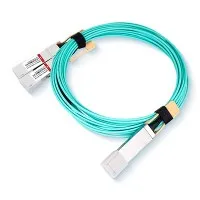
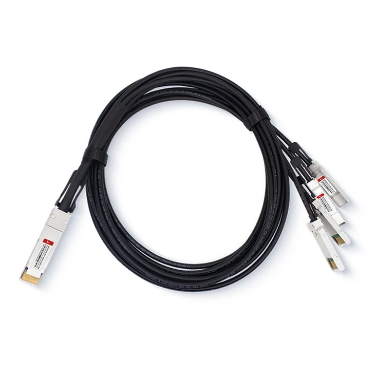
1. What is the function of the 100G QSFP28 to 4x25G SFP28 Breakout AOC Active Optical Cable?
A: The 100G QSFP28 to 4x25G SFP28 Breakout AOC Active Optical Cable is designed to convert electrical signals to optical signals and vice versa during communication. It features a QSFP28 connector at one end and four SFP28 connectors at the other, providing four independent data transmission channels, each capable of operating at up to 25.78125 Gbps.
2. What is the maximum transmission distance of this cable?
A: The maximum transmission distance of the 100G QSFP28 to 4x25G SFP28 Breakout AOC Active Optical Cable can reach up to 100 meters on OM4 MMF.
Hot Tags: 100g qsfp28 to 4x25g sfp28 breakout aoc active optical cable, China 100g qsfp28 to 4x25g sfp28 breakout aoc active optical cable manufacturers, suppliers, factory, SFP-10G-LR, SFP-10G-BIDI-1490-80, , SFPDD 100G DAC 1 10 M, SFP28-25G-SR, QSFP28-2X50G-DAC