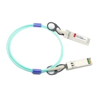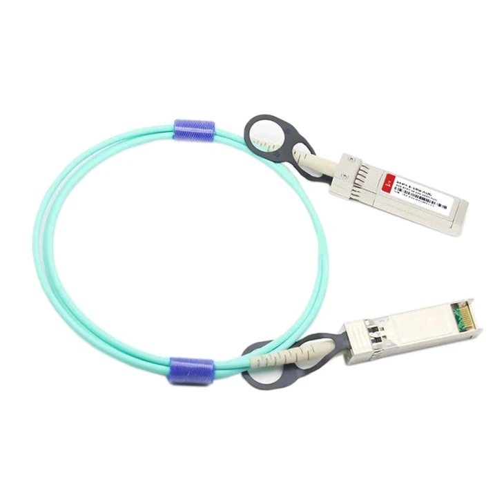
D-Net`S Active Optical Cable Service
● Compatibility Assistance: D-NET offers compatibility services to ensure optical modules are compatible with equipment from leading manufacturers.
● Personalized Services: D-NET provides OEM customization options for its products. Upon request, customers can have colored logo labels tailored to their needs.
● Standard Delivery Period: 3 Days
● Extensive Shipping Solutions: D-NET collaborates with highly reputable courier companies such as SF, FedEx, DHL, UPS, and others to ensure reliable shipping services.
Features
● Electrical interface compliant to SFF-8431
● 850nm VCSEL laser and PIN photo-detector
● Maximum link length of 70m on OM3 MMF and 100m on OM4 MMF
● Digital diagnostics functions are available via the I2C interface
● RoHS compliant
● Hot Pluggabl
Applications
● 25GBASE-SR Ethernet
● InfiniBand QDR, SDR, DDR
● Servers, switches, storage and host card adapters
Outline drawing

|
Parameter |
Value |
Units |
|
Diameter |
3 |
mm |
|
Minimum bend radius |
30 |
mm |
|
Length tolerance |
Length < 1 m: +5 /-0 |
cm |
|
1 m ≤length ≤ 4.5 m: +15 / -0 |
cm |
|
|
5 m ≤length ≤ 14.5 m: +30 / -0 |
cm |
|
|
Length≥15.0 m +2% / -0 |
m |
|
|
Cable color |
Aqua(OM3),Megenta(OM4) |
|
Wiring Diagram
pin design:

Pin Descriptions:
|
Pin |
Symbol |
Name/Description |
Notes |
|
1 |
VEET |
Module Transmitter Ground |
1 |
|
2 |
TX_FAULT |
Module Transmitter Fault |
2 |
|
3 |
TX_DISABLE |
Transmitter Disable; Turns off transmitter laser output |
3 |
|
4 |
SDA |
2-Wire Serial Interface Data Line (MOD-DEF2) |
|
|
5 |
SCL |
2-Wire Serial Interface Clock (MOD-DEF1) |
|
|
6 |
MOD_ABS |
Module Absent, connected to VEET or VEER in the module |
2 |
|
7 |
RS0 |
Rate Select 0, optionally controls SFP+ module receiver |
|
|
8 |
RX_LOS |
Receiver Loss of Signal Indication (In FC designated as Rx_LOS and in Ethernet designated as NOT Signal Detect) |
2 |
|
9 |
RS1 |
Rate Select 1, optionally controls SFP+ module transmitter |
|
|
10 |
VEER |
Module Receiver Ground |
1 |
|
11 |
VEER |
Module Receiver Ground |
1 |
|
12 |
RD- |
Receiver Inverted Data Output |
|
|
13 |
RD+ |
Receiver Non-Inverted Data Output |
|
|
14 |
VEER |
Module Receiver Ground |
1 |
|
15 |
VCCR |
Module Receiver 3.3 V Supply |
|
16 |
VCCT |
Module Transmitter 3.3 V Supply |
|
|
17 |
VEET |
Module Transmitter Ground |
1 |
|
18 |
TD+ |
Transmitter Non-Inverted Data Input |
|
|
19 |
TD- |
Transmitter Inverted Data Input |
|
|
20 |
VEET |
Module Transmitter Ground |
1 |
Remake:
1. The module ground pins are isolated from the module case.
2. The pins shall be pulled up with 4.7K-10Kohms to a voltage between 3.14V and 3.46V on host board.
3. The pin is pulled up to VCCT with a 4.7K-10KΩ resistor in the module.
Recommended Operating Conditions
|
Parameter |
Symbol |
Min. |
Typical |
Max. |
Unit |
Notes |
|
Operating Case Temperature |
TC |
0 |
- |
+70 |
°C |
|
|
Power Supply Voltage |
Vcc |
3.14 |
3.3 |
3.47 |
V |
|
|
Power Supply Current |
Icc |
- |
- |
300 |
mA |
|
|
Power Dissipation |
Pd |
- |
- |
1.0 |
W |
|
|
Bit Rate |
BR |
8.5 |
25.78125 |
- |
Gbps |
|
|
Fiber Bend Radius |
Rb |
3 |
- |
- |
cm |
Electrical Characteristics
|
Parameter |
Symbol |
Min. |
Typ. |
Max. |
Units |
Notes |
||
|
Transmitter |
||||||||
|
Differential Data Input Swing |
Vin,P-P |
200 |
- |
1600 |
mVPP |
|||
|
Input Differential Impedance |
ZIN |
90 |
100 |
110 |
Ω |
|||
|
Tx_Fault |
Normal Operation |
VOL |
0 |
- |
0.8 |
V |
||
|
Transmitter Fault |
VOH |
2.0 |
- |
VCC |
V |
|||
|
Tx_Disable |
Nor0mal Operation |
VIL |
0 |
- |
0.8 |
V |
||
|
Laser Disable |
VIH |
2.0 |
- |
VCC+0.3 |
V |
|||
|
Receiver |
|||||||
|
Differential Date Output |
Vout |
400 |
- |
800 |
mV |
||
|
Output Differential Impedance |
ZD |
90 |
100 |
110 |
Ω |
||
|
Rx_LOS |
Normal Operation |
VOL |
0 |
- |
0.8 |
V |
|
|
Lose Signal |
VoH |
2.0 |
- |
VCC |
V |
||
Products Description
|
Parameter |
Symbol |
Unit |
Min |
Typ |
Max |
Notes |
|
Optical transmitter Characteristics |
||||||
|
Data Rate |
DR |
Gbps |
8.5 |
25.78125 |
||
|
Center Wavelength Range |
λc |
nm |
820 |
850 |
880 |
|
|
Laser Off Power |
Poff |
dBm |
- |
- |
-45 |
|
|
Launch Optical Power |
P0 |
dBm |
-6.0 |
2.4 |
||
|
Extinction Ratio |
ER |
dB |
2 |
- |
- |
|
|
(rms) Spectral Width(RMS) |
RMS |
nm |
- |
0.65 |
||
|
Optical Receiver Characteristics |
||||||
|
Data Rate |
DR |
Gbps |
8.5 |
25.78125 |
||
|
Bit Error Rate |
BER |
dBm |
- |
- |
E-12 |
|
|
Damage threshold |
DT |
dBm |
3.4 |
- |
- |
|
|
Overload Input Optical Power |
PIN |
dBm |
2.4 |
- |
- |
|
|
Center Wavelength Range |
λc |
nm |
820 |
- |
880 |
|
|
Receiver Sensitivity in Average Power |
Sen |
dBm |
- |
- |
-5.2 |
|
|
Los Assert |
LosA |
dBm |
-30 |
- |
- |
|
|
Los De-Assert |
LosD |
dBm |
- |
- |
-13 |
|
|
Los Hysteresis |
LosH |
dB |
0.5 |
- |
- |
Absolute Maximum Ratings
|
Parameter |
Symbol |
Min. |
Typical |
Max. |
Unit |
Notes |
|
Supply Voltage |
Vcc3 |
-0.5 |
- |
+3.6 |
V |
|
|
Storage Temperature |
Ts |
-40 |
- |
+85 |
°C |
|
|
Operating Humidity |
RH |
+5 |
- |
+85 |
% |
FAQ
1. What type of connectors does the 25G SFP28 AOC use?
A: The 25G SFP28 AOC uses SFP28 connectors, which are hot-pluggable and compliant with the SFP28 MSA and IEEE 802.3by 25GBASE-SR Ethernet standards.
2. What are the power consumption and power supply voltage specifications for the 25G SFP28 AOC?
A: Each SFP28 module in the 25G SFP28 AOC has a maximum power consumption of less than 1W, and the power supply voltage is 3.3V.
3. How does the 25G SFP28 AOC ensure compatibility with different network devices?
A: The 25G SFP28 AOC is designed to be compatible with a wide range of network devices from various vendors such as Huawei, H3C, Cisco, Dell, and more. Each product undergoes real-device testing to verify its compatibility and ensure stable operation.
Hot Tags: 25g sfp28 aoc active optical cable, China 25g sfp28 aoc active optical cable manufacturers, suppliers, factory, SFP-10G-ZR, , QSFP56-2X100G-AOC, QSFP28-100G-SR4, SFP-10G-BIDI-1330-10, SFP28-25G-SR